A surface-emitting laser incorporating a high-index-contrast subwavelength grating
MICHAEL C.Y. HUANG, Y. ZHOU AND CONNIE J. CHANG-HASNAIN*
Department of Electrical Engineering and Computer Sciences, University of California at Berkeley, California 94720, USA
*e-mail: cch@eecs.berkeley.edu
Published online: 1 February 2007; doi:10.1038/nphoton.2006.80
Semiconductor diode lasers can be used in a variety of applications including telecommunications, displays, solid-state lighting, sensing and printing. Among them, vertical-cavity surface-emitting lasers1–3 (VCSELs) are particularly promising. Because they emit light normal to the constituent wafer surface, it is possible to extract light more efficiently and to fabricate two-dimensional device arrays. A VCSEL contains two distributed Bragg reflector (DBR) mirrors for optical feedback, separated by a very short active gain region. Typically, the reflectivity of the DBRs must exceed 99.5% in order for the VCSEL to lase. However, the realization of practical VCSELs that can be used over a broad spectrum of wavelengths has been hindered by the poor optical and thermal properties of candidate DBR materials4–6. In this Letter, we present surface-emitting lasers that incorporate a single-layer high-index-contrast subwavelength grating7,8 (HCG). The HCG provides both efficient optical feedback and control of the wavelength and polarization of the emitted light. Such integration reduces the required VCSEL mirror epitaxial thickness by a factor of two and increases fabrication tolerance. This work will directly influence the future designs of VCSELs, photovoltaic cells and light-emitting diodes at blue –green, 1.3 –1.55 mm and mid- to far-infrared wavelengths.
Broadband mirrors with high reflectivity are essential for constructing a VCSEL cavity with a high quality factor. They are typically composed of semiconductor DBRs, structures formed from multiple layers of alternating dielectric materials with periodic variation of refractive indices. Their reflectivity and bandwidth depend on the refractive-index contrast of the constituent materials and the precision of thickness control within each layer. Because of epitaxial growth constraints for matching the material atomic lattice, typical combinations of DBR materials often have small refractive-index differences. Thus, it is often necessary to have a rather large number of DBR pairs (25–40) to attain a high enough reflectivity in addition to the resulting small mirror bandwidth (Dl/l 3 –9% where l is the wavelength of the light). This has been one of the major difficulties in current VCSEL fabrication, especially for blue–green and long-infrared wavelengths. The problem becomes more challenging when making wavelength-tunable VCSELs, where the requirements on mirror bandwidth and reflectivity are even more stringent9.
To overcome the limitation of DBRs in surface-emitting optoelectronic devices, we propose and demonstrate the use of a single-layer, high-index-contrast subwavelength grating in place of a conventional DBR. For example, 35–40 pairs of GaAs–AlGaAs DBRs approximately 5 mm in thickness can be replaced by a 0.235 mm thick AlGaAs-based HCG with an equivalent reflectivity. Thus, by using an HCG, we can potentially reduce the required VCSEL mirror epitaxial thickness and simplify material growth requirements for achieving thickness and composition accuracy7. The HCG differs from a second-order grating both in terms of structural design and in performance, in that coupling efficiency and reflectivity are both significantly lower10. Furthermore, the HCG reflectivity bandwidth is 10 times wider than that of a conventional DBR7 and indeed 100 times wider than that of a second-order grating11. In earlier work we have reported theoretical calculations and experimental reflectivity measurements of a single HCG mirror7,8. However, it was difficult to determine the absolute value of the reflectivity, the phase delay and the dependence on beam divergence, which are all critical for VCSEL design. It was therefore uncertain whether an HCG was suitable for integration with a VCSEL structure to be used in the near-field regime. In this paper we demonstrate, for the first time, the realization of a VCSEL with an HCG mirror (HCG-VCSEL).
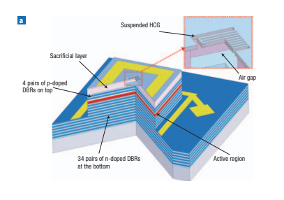
The schematic of the device is shown in Fig. 1a. The device consists of a conventional semiconductor-based bottom n-DBR mirror, a l-cavity layer containing the active region and an HCG-based top mirror. The top mirror is composed of two parts: a four-pair p-doped DBR and a freely suspended HCG. The p-DBR
is mainly used to provide current spreading while protecting the active region during fabrication. Although the p-DBR does increase the overall reflectivity of the top mirror, our simulation shows that the number of p-DBR pairs can be reduced, because a single-layer HCG, as the top mirror, is capable of providing sufficient reflectivity (R . 99.9%). Electric-current injection is carried out through the top contact (through the p-doped HCG layer) and the bottom contact (through the n-DBR). An aluminium oxide aperture, formed from the thermal oxidation of an AlGaAs layer in the p-DBR section immediately above the cavity layer, provides efficient current and optical confinement12. Figure 1b shows the scanning electron microscope (SEM) image of the fabricated HCG-integrated VCSEL, where the HCG is defined in the centre of the VCSEL mesa, aligned with the oxide aperture. Figure 1c and d shows close-up views of the freely suspended HCG structure. A stress-relief trench surrounding the grating was necessary to eliminate buckling of the suspended

Figure 1 VCSEL integrated with an HCG. a, Schematic cross-sectional layout of the VCSEL with the top mirror consisting of a freely suspending HCG and four pair DBRs. b, SEM image of a fabricated HCG-integrated VCSEL, where the grating is aligned with the centre of the device mesa. c, Close-up SEM image of the freely suspended grating, where a stress-relief trench is used to eliminate buckling of the grating. d, Zoomed-in SEM image of the fabricated individual grating stripes.
gratings after the release process, which occurs as a result of residual stress in the material.
The structure of the HCG consists of periodic stripes of Al0.6Ga0.4As that are freely suspended with air as the low-index cladding layers on the top and bottom. The high- and low-index materials denoted as nH and nL, have refractive indices of 3.2 and 1 respectively. The grating has the following parameters: period (L) 1⁄4 0.375 mm, thickness (tg) 1⁄4 0.235 mm, duty cycle (DC) 1⁄4 62%, airgap thickness (tL) 1⁄4 1.05 mm (5l/4) and area 1⁄4 10 mm 10 mm. The DC is defined as the ratio of the width of the high-index material to the grating period. Hence it is determined by the width of the gap between the grating, or equivalently the critical lithography dimension, which is nominally 140 nm. As the HCG design is configured with one- dimensional symmetry, it is polarization-sensitive; transverse- magnetic (TM)-polarized light with its electric field perpendicular to the grating lines sees much higher reflectivity than the transverse-electric (TE)-polarized light. Figure 2a and b shows a reflectivity simulation of the VCSEL top mirror using calculations based on the rigorous coupled wave analysis method (ref. 13) for TM- and TE-polarized incident waves normal to the surface, respectively. The surface plot illustrates that a sufficient index ratio (nH/nL . 2) is required between the constituent materials in the grating in order to achieve high reflectivity and broad bandwidth. In our design where nH/nL 1⁄4 3.2, the reflectivity for the TM polarized light is .99.9% for wavelength ranges of 0.8–0.88 mm,whereas that for TE-polarized light is only 95%. As a reflectivity value of 99.5% is typically required for a VCSEL to lase, the HCG is therefore an excellent candidate for serving as the top mirror of a VCSEL, and has the added benefit of polarization control. In contrast, it is calculated that the reflectivity of a top mirror consisting only of four pairs of fixed DBRs is at most about 70%.
The physical origin for the high reflectivity of TM-polarized light is summarized below. We use an idealized transverse electromagnetic (TEM) wave for the explanation, as this is the orthonormal set that can be used to express any wavefunction. The high reflectivity stems from meeting the boundary conditions of both the propagating displacement (D 1⁄4 n2 E) and electric (E) fields. The Eparallel field becomes Dnormal. as the field enters the grating. As a result of the large index contrast and the continuity
of Dnormal, an in-plane propagating wave is excited, which sees a large index modulation and produces a high reflection with a large bandwidth. This in-plane propagating wave, in turn, also needs to meet the same boundary conditions as it is reflected by the grating, which thus couples back to the surface-normal TM- polarized TEM wave.
Continuous-wave operation of an HCG-VCSEL has been demonstrated for the first time at room temperature. Figure 3a shows the HCG-VCSEL device characteristics for output power versus the input current (LI) and voltage versus input current (IV). The device exhibits excellent performance, with a low lasing threshold current of 0.8 mA and output power of 1 mW,approximately half the threshold and twice the power efficiency compared with that of standard commercial VCSELs grown by the same epitaxy manufacturer (Land Mark Optoelectronics Corporation; http://www.lmoc.com.tw/) with an identical active region and n-DBR design. These results indicate that an HCG has been obtained experimentally with reflectivity exceeding 99.5%, equivalent to the reflectivity from 30 pairs of DBRs. The output power is currently limited by thermal effects, as indicated by the large dynamic resistance leading to early thermal roll- off behaviour.
The HCG-VCSEL emission has a TM-polarization preference because the HCG reflectivity is polarization-dependent. The laser LI characteristic is plotted in decibels for both the TM and TE polarization, shown in the inset in Fig. 3a. It is evident that an HCG can provide lithographically determined polarization control, for example, with an orthogonal polarization suppression ratio (OSPR) of 20 dB. This intrinsic polarization selectivity can be used to control the polarization of the VCSEL and so minimize the polarization-dependent noise of the output VCSEL light14. Compared with other VCSEL polarization-control techniques15–17, the inherent reflectivity difference between TM- and TE-polarized light in the HCG results in a large polarization-dependent modal loss. Equivalently, the calculated threshold gain required for the TE polarization (gth, TE) is approximately four times larger than that required for the TM polarization (gth, TM 1⁄4 740 cm21).
The emission spectra of the HCG-VCSEL under various injected currents are shown in Fig. 3b. Single-mode emission was obtained where higher-order transverse modes were suppressed
by a power ratio of 45 dB, which can be attributed to the optical confinement of the aluminium oxide aperture and a size- dependence of the HCG reflectivity. The centre wavelength corresponds to the designed Fabry –Perot cavity wavelength; hence the HCG is phase-matched to the rest of the optical cavity. Owing to thermal heating effects, the device exhibits a larger wavelength-dependence on the input current than a typical VCSEL, which can be improved with proper thermal engineering. The emission spectra for control VCSELs with grating DCs of 0% and 100% are shown together with that for an HCG-VCSEL in Fig. 4. A DC of 0% corresponds to having no HCG layer, and a DC of 100% indicates that an additional uniform layer of AlGaAs

Figure 2 Simulated reflectivity of the HCG-based VCSEL. The HCG in the top mirror consists of high- and low-index materials with various refractive index ratios (nH/nL). a,b, Reflectivity as a function of wavelength for TM-polarized (a) and TE-polarized (b) incident plane waves normal to the surface. In our design, where nH/nL 1⁄4 3.2, the reflectivity for the TM-polarized light is .99.9% for the wavelength range 0.8 –0.88 mm, but the reflectivity for TE-polarized light is only 95% for the same wavelength range.

Figure 3 Optical characteristics of an HCG-based VCSEL. a, Output light intensity as a function of the input current, and voltage as a function of the input current.
The inset shows the polarization-resolved output power plotted in dB scale as a function of the input current for the TM and TE emission light, showing a polarization
suppression ratio of 20 dB. b, Measured single-mode emission spectra under different bias currents, showing a 45 dB suppression of higher-order transverse modes.

Figure 4 Emission spectra of the VCSEL with and without the HCG. The control VCSELs were tested with duty cycles (DCs) of 0% and 100%. A DC of 0% corresponds to having no HCG layer, and a DC of 100% indicates that an additional uniform layer of AlGaAs is used to provide extra reflectivity. The results show that only when an HCG is implemented does a VCSEL have sufficient reflectivity from the top mirrors to achieve lasing.
is used to provide extra reflectivity. The emission for those control devices is strongly dominated by spontaneous emission from the active region, indicating that merely a four-pair DBR or the addition of a single uniform high-index layer cannot provide sufficient reflectivity for a VCSEL to achieve lasing. We further experimentally varied the DC of the HCG-VCSEL by lithographically changing the width of the gap between the gratings. Devices with a grating DC ranging from 73 to 84%, corresponding to a critical dimension (grating gap) of between 60 and 100 nm, all lased with similar threshold currents, indicating a very large tolerance of+25% for the critical lithography dimension of 80 nm. The discrepancy in the grating gap dimension between simulation and experiment is explained in the Methods.
We demonstrate a VCSEL using an integrated single-layer high-index-contrast subwavelength grating as its top mirror, with air and AlGaAs as the low- and high-index materials, respectively. The VCSEL exhibits low threshold current, deterministic polarization and single transverse mode. We also show a theoretical guideline for the index contrast in the HCG, which opens up various material combination possibilities. For instance, a low-index dielectric such as SiO2 or Al2O3 can be used instead of air as the low-index material under the grating. The simplicity, wavelength scalability and versatility of the single-layer HCG design could provide numerous benefits when fabricating surface-normal optoelectronic devices, such as VCSELs, high-brightness LEDs, photovoltaic cells, optical filters and detectors and micro-electromechanical (MEMS) tunable devices, for a wide range of wavelengths.
METHODS
The fabrication process for the HCG-integrated VCSEL was similar to that of a standard VCSEL, including two metal depositions, mesa formation etch, thermal oxidation and the HCG definition. The HCG was patterned by electron-beam lithography on poly-methyl methacrylate photoresist, which provides design flexibility in terms of L and DC. The lithography patterns were then transferred through a reactive ion etching process. Owing to non-idealistic grating sidewall undercut etching from our particular etching process, the grating had an inverted trapezoidal profile with a sidewall angle of 858 instead of the perfect rectangular profile used in the simulation. Consequently, the required fabricated device critical dimension (60 –100 nm) was smaller than the nominal value obtained from the simulation (140 nm). Finally, a chemical-based selective etch followed by CO2 critical point drying removed the sacrificial material under the HCG layer and formed the freely suspended grating structure.
Received 27 July 2006; accepted 1 December 2006; published 1 February 2007.
References
- Iga, K. Surface-emitting laser — its birth and generation of new optoelectronics field. IEEE J. Sel.Top. Quant. Electron. 6, 1201–1215 (2000).
- Wilmsen, C. W., Temkin, H. & Coldren, L. A. Vertical-Cavity Surface-Emitting Lasers: Design,Fabrication, Characterization, and Applications (Cambridge Univ. Press, New York, 1999).
- Cheng, J. & Dutta, N. K. Vertical-Cavity Surface-Emitting Lasers: Technology and Applications(Gordon & Breach, Amsterdam, 2000).
- Chang-Hasnain, C. J., in Optical Fiber Telecommunications (eds Kaminow, I. & Li, T.) 666 –698(Academic Press, San Diego, 2002).
- Karim, A., Bjorlin, S., Piprek, J. & Bowers, J. E. Long-wavelength vertical-cavity lasers and amplifiers. IEEE J. Sel. Top. Quant. Electron. 6, 1244–1253 (2000).
- Nishiyama, N. et al. Long-wavelength vertical-cavity surface-emitting lasers on InP with lattice matched AlGaInAs – InP DBR grown by MOCVD. IEEE J. Sel. Top. Quant. Electron. 11, 990–998 (2005).
- Mateus, C. F. R., Huang, M. C. Y., Deng, Y., Neureuther, A. R. & Chang-Hasnain, C. J. Ultrabroadband mirror using low-index cladded subwavelength grating. IEEE Photon. Technol.Lett. 16, 518–520 (2004).
- Mateus, C. F. R., Huang, M. C. Y., Lu, C., Chang-Hasnain, C. J. & Suzuki, Y. Broad-band mirror (1.12–1.62 mm) using a subwavelength grating. IEEE Photon. Technol. Lett. 16, 1676–1678 (2004).
- Chang-Hasnain, C. J. Tunable VCSEL. IEEE J. Sel. Top. Quant. Electron. 6, 978 –987 (2000).
- Hardy, A., Welch, D. F. & Streifer, W. Analysis of second-order gratings. IEEE J. Quant. Electron. 25, 2096–2105 (1989).
- Cheben, P. et al. A broad-band waveguide grating coupler with a subwavelength grating mirror.IEEE Photon. Technol. Lett. 18, 13 –15 (2006).
- Choquette, K. D. et al. Advances in selective wet oxidation of AlGaAs alloys. IEEE J. Sel. Top.Quant. Electron. 3, 916–926 (1997).
- Moharam, M. G. & Gaylord, T. K. Rigorous coupled-wave analysis of planar-grating diffraction.J. Opt. Soc. Am. 71, 811–818 (1981).
- Chang-Hasnain, C. J. et al. Dynamic, polarization, and transverse mode characteristics of vertical cavity surface emitting lasers. IEEE J. Quant. Electron. 27, 1402–1409 (1991).
- Haglund, A., Gustavsson, J. S., Bengtsson, J., Jedrasik, P. & Larsson, A. Design and evaluation of fundamental-mode and polarization-stabilized VCSELs with a subwavelength surface grating.IEEE J. Quant. Electron. 42, 231 –240 (2006).
- Ostermann, J. M., Debernardi, P. & Michalzik, R. Optimized integrated surface grating design for polarization-stable VCSELs. IEEE J. Quant. Electron. 42, 690–698 (2006).
- Schablitsky, S. J., Zhuang, L., Shi, R. C. & Chou, S. Y. Controlling polarization of vertical-cavity surface-emitting lasers using amorphous silicon subwavelength transmission gratings. Appl. Phys.Lett. 69, 7–9 (1996).
Acknowledgements
This project was supported by the DARPA Center for Optoelectronic Nanostructure Semiconductor Research and Technology (CONSRT). We thank Land Mark Optoelectronics Corporation for the growth of the epitaxy wafer and Berkeley Microfabrication Laboratory for the fabrication support. Correspondence and requests for materials should be sent to C.C.H.
Competing financial interests
The authors declare that they have no competing financial interests.
Reprints and permission information is available online at http://npg.nature.com/reprintsandpermissions/

