Long-Wavelength VCSEL Using High-Contrast Grating
Yi Rao, Student Member, IEEE, Weijian Yang, Student Member, IEEE, Christopher Chase, Michael C. Y. Huang,
D. Philip Worland, Salman Khaleghi, Mohammad Reza Chitgarha, Morteza Ziyadi,
Alan E. Willner, Fellow, IEEE, and Connie J. Chang-Hasnain, Fellow, IEEE
Abstract—Recent advances in high-contrast grating (HCG) vertical-cavity surface-emitting lasers (VCSEL) emitting at 1550 nm is reported in this paper. The novel near-wavelength HCG has an ultrathin structure and broadband reflectivity. It enables a monolithic, simple fabrication process for realizing InP-based VCSELs emitting at ∼1550 nm. We report 2.4-mW single-mode output under continuous-wave operation at 15 ◦C. We show that, despite broadened by the Brownian motion, the HCG-VCSEL has a total linewidth of 60 MHz or a coherent length of 5 m in air, and an intrinsic linewidth <20 MHz. Transmission of directly mod- ulated 10 Gbps over 100-km dispersion-compensated single-mode
fiber is demonstrated. Tunable HCG-VCSEL is demonstrated with the HCG integrated with a micro-electro-mechanical structure. Continuous wavelength tuning as wide as 26.3 nm is achieved. The tunable VCSEL was used as a source for external modulation for 40-Gbps differential-phase-shift-keyed signal and transmitted over 100-km dispersion-compensated link with negligible power penalty.
Index Terms—High-contrast subwavelength grating, laser linewidth, optical MEMS, optical communication, vertical-cavity surface-emitting laser (VCSEL).
I. INTRODUCTION
VERTICAL-cavity surface-emitting lasers (VCSELs) are key optical sources in optical communications, the dominant source deployed in local area networks using multimode optical fibers at 850 nm. The advantages of VCSELs include wafer-scale testing, low-cost packaging, and ease of fabrication into arrays. The ease of array fabrication is particularly useful for space-division-multiplexed (SDM) links using multicore fiber or fiber arrays. VCSELs emitting in the 1.3– 1.6 μm wavelength regime, also known as long-wavelength VCSELs, are highly desirable for the rising applications of
data and computer communications, in addition to optical ac- cess networks, optical interconnects, and optical communication among wireless base stations. The potential advantages over conventional distributed feedback (DFB) and distributed Bragg reflector (DBR) lasers include much lower cost due to smaller footprint and wafer-scale testing, and significantly lower power consumption [1]. InP-based long-wavelength VCSELs have been demonstrated using techniques such as metamorphic GaAs DBR [2], buried tunnel junction [3], [4], substrate removal [5], and multisteps wafer fusion [6], [7] in the last ten years. However, all of these solutions require complex, expensive manufacturing processes. To date, long-wavelength InP-based VCSELs have not made major inroads on the market. Designing a device structure that can be manufactured as cost-effective as 850-nm GaAs-based VCSELs remains a major challenge.
Tunable light sources are important for wavelength division multiplexing (WDM) systems with applications including sparing, hot backup, and fixed wavelength laser replacement for inventory reduction [8]. They give network designers another degree of flexibility to drive down overall system cost. Such con- siderations are especially important for fiber-to-the-home and data center applications. Additionally, mode-hop-free, fast and widely tunable light sources are a perfect candidate for optical coherent tomography (OCT) [9] and light ranging applications [10]. Tunable VCSELs using micro-electro-mechanical structures (MEMS) are desirable because of their continuous tuning characteristics, making them promising for low-cost manufacturing and low-power consumption [11]. Although many structures have been reported with wide, continuous tuning range [9], [12], [13], largely due to their fabrication complexity, low-cost tunable 1550-nm VCSELs have not yet been available on the market.
In this paper, we report the first high-speed 1550-nm VCSEL and tunable VCSEL using a high-contrast grating (HCG) as the top mirror. A planar process of proton implant is used to provide current confinement, leading to a wafer-scale, low-cost fabrication process. Direct modulation up to 10 Gbpsand transmission over a 100-km dispersion-compensated singlemode fiber (SMF) link are demonstrated using an HCG-VCSEL.

Tunable HCG-VCSELs show a continuous tuning range of 26.3 nm with >1.4-mW single-mode output under room temper ature continuous-wave (CW) operation over most of the tuning range.
MEMS-based tunable VCSELs had previously been shown to exhibit broadened linewidths typically on the order of a few hundreds of megahertz to gigahertz due to mechanical fluctuation of MEMS caused by the Brownian motion [14], [15]. This could be problematic for applications requiring laser coherence linewidth < 100 MHz or length >3 m in free space. In this paper, we investigate this particular issue using self-heterodyne measurement with various delay lengths, and provide a new per- spective to the linewidth of the HCG and MEMS VCSEL. We show that a 60 MHz total linewidth and a <20-MHz intrinsic linewidth are extracted from the measurements for the first time. In addition, using the tunable VCSEL as a CW source for ex- ternal modulation, we demonstrated error-free transmission of 40-Gbps differential-phase-shift-keyed (DPSK) signals through a dispersion-compensated 100-km SMF link.This paper is organized as follows. The basic concept of HCG is briefly reviewed, followed by the design, fabrication, and characteristics of HCG VCSELs under CW operation. We then discuss the linewidth measurement of the HCG-VCSEL. Next, we discuss the design, fabrication, and electrical and optical characteristics of high speed directly modulated VCSELs and tunable VCSELs. Finally, we show the transmission measurements using the tunable VCSEL as a CW source for an external modulator.
II. CONCEPT OF HIGH-CONTRAST GRATING
The HCG is a single layer of near-wavelength grating consisting of high refractive-index material grating bars fully sur- rounded by low-index materials, shown in Fig. 1(a) [16]–[18]. By near-wavelength, we mean that the grating period is bounded by the limits of one wavelength in air and the high-index medium [18]. This unique dimension constraint and refractive-index contrast results in extraordinary properties [18]. In this particular case for VCSELs, we design the HCG to exhibit broadband, high reflectivity for surface-normal incident light with polarization either parallel or orthogonal to the gratings (y-direction), also known as transverse electric (TE), and transverse magnetic (TM) light, respectively. Fig. 1(b) and (c) shows the surface normal reflection spectrum of a TE-HCG and TM-HCG calculated with the HCG analytical solution [16]–[18]. The HCG reflectivity, shown in Fig. 1(b), is optimized for TE-polarization (>99% reflectivity over a more than 100-nm wavelength range). In contrast, when the HCG is optimized for TM-polarization, shown in Fig. 1(c), the TM-polarization has 99% reflectivity over 150 nm.In either case, the reflectivity of the other polarization is low. As shown in the later section, this reflectivity difference can descriminate different polarization modes, and thus polarization mode selection in HCG-VCSELs is easy and flexible. In addition, the reflectivity of HCG at a specific wavelength range can be designed by varying the duty cycle, period, and thickness of HCG, so that arbitrary reflectivity between 98% and 100% can be achieved by different grating design [19].
To understand the broadband high reflectivity phenomenon,the electromagnetic field profile inside the grating can neither be approximated nor ignored. Recently, we published a simple analytic formulism to explain the broadband high reflection [16]–[18]. Here we provide a brief review.
The grating bars can be considered as a periodic array of waveguides along the z-direction. Upon plane wave incidence,only a few waveguide array modes are excited. Due to a largeindex contrast and near-wavelength dimensions, there exists a wide wavelength range where only two modes have real propagation constants in the z-direction and, hence, carry energy. This is the regime of interest, and is referred as the dual-modregime. The two modes then depart from the grating input plane(z = 0) and propagate downward (+z-direction) to the grating output plane (z = tg ), and then reflect back up. If the HCG is properly designed such that the two modes carry similar energy but opposite phases at the HCG output plane, destructive interference occurs. This cancels the transmission and thus all of the power must be reflected. Note that only the zeroth diffraction order carries energy due to the subwavelength period in air The broadband property is attributed by the high-index contrast between the grating bars and the surrounding medium.
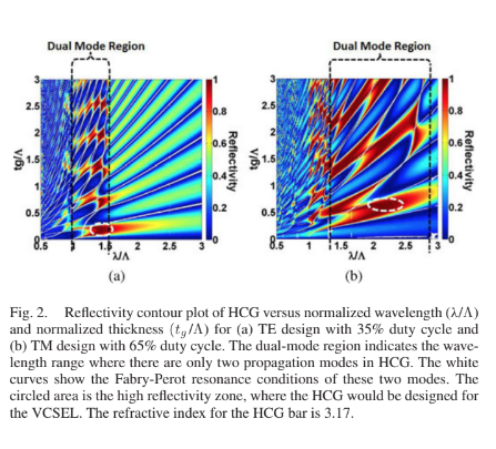
Fig. 2 shows the reflectivity contour plot of the TE- and TM-HCG versus normalized wavelength and grating thickness (both normalized by Λ). A well-behaved, highly ordered,
checker-board pattern reveals its strong property dependence on both wavelength and HCG thickness, which indicates an interference effect. This checker-board pattern is particularly pronounced in the dual-mode regime, where there are only two propagation modes in HCG. The Fabry–Perot resonance conditions of these two modes are shown by the white curves. A detailed and comprehensive explanation of HCG physics can be found in [18].


for TM-HCG (η = 0.65), the desirable tg /Λ is ∼0.6, and λ/Λ is ∼2.2 We experimentally demonstrated the broadband high reflectivity with an Si HCG on top of SiO2 in 2004 [20]. In 2007, we applied this novel HCG concept on an 850-nm VCSEL [21], and demonstrated room temperature CW operation with an HCG reflectivity greater than 99%. Later, in 2008, we reported MEMS-tunable HCG-VCSELs with a 20-nm tuning range and 27-MHz tuning speed [22], [23]. The 1550-nm InP-based HCG-VCSEL was demonstrated in 2010 [24]. Many advances of HCG-VCSELs and lasers have been reported since 2008 [25]–[28]. In the following sections, we will focus on the discussion on 1550-nm HCG-VCSELs.
III. 1550-NM HCG-VCSEL DESIGN AND FABRICATION
The GaAs-based 850-nm VCSELs are manufactured costeffectively in wafer-scale largely attributed to the fact that they can be made with one single epitaxy and simple device definition for current confinement. However, it has been difficult to fabricate long-wavelength VCSELs with one single epitaxy because of complex process needed for current confinement and challenges in obtaining high reflectivity DBR with high ther mal conductance. Using an ultrathin HCG structure, we showed that a planar and monolithic process of proton implantation can be used to provide current confinement in 1550-nm HCGVCSELs [24]. This is made possible because of the relatively thin thicknesses of the HCG and sacrificial layer. Additionally, a tunnel junction is used to minimize the amount of p-type materials, thus reducing the free carrier absorption and electrical resistance.
The schematic of an HCG-VCSEL lasing at 1550 nm is shown in Fig. 3, where the HCG grating is fully suspended in air. The as-grown epitaxial wafer consists of 40–55 pairs of bottom nDBR, an active region, p-type cladding, tunnel junction, sacrificial layer, HCG layer, and top contact layer. The current aperture is defined by 300–400 keV H+ implant depending on the thickness of the sacrificial layer. The diameter of the current aperture varies from 8 to 20 μm depending on the specific design. An annular top contact and uniform bottom contact are deposited by electron beam evaporation. After the formation of top and bottom contact, a mesa is defined by wet chemical etching, so the devices are electrically isolated from each other. The HCG is defined by electron beam lithography and followed by anisotropic vertical etching. Finally, the HCG structure is released by wet chemical etching and critical point drying. Scanning electron microscope (SEM) images of a completed HCG-VCSEL are shown in Fig. 4.
IV. CONTINUOUS-WAVE OPERATION OF THE 1550-NM HCG-VCSEL
The VCSELs have excellent CW performance characteristics. Fig. 5(a) shows the temperature dependent light–currentvoltage (LIV) characteristic of a TE-HCG-VCSEL with continuous output power of 2.4 mW at 15 ◦C and 0.5 mW at 85 ◦C. The devices have slope efficiencies of ∼0.25 mW/mA and threshold currents of <1 mA at 15 ◦C. The spectral characteristics are shown in Fig. 5(b) with fixed bias current I = 4Ith at different temperatures, which is a single polarization mode from 15 to 85 ◦C. The device has a bias voltage of 2.2 V at 20 mA, indicating 50–60 Ω of series resistance. The resistance could be further reduced by optimizing the doping level in the current spreading layer as well as the proton implant condition. The wall-plug efficiency is 10% at 15 ◦C, which is mainly limited by the relatively high voltage and series resistance. Another unique property of the HCG-VCSEL is the singlemode preference. The VCSEL shown in Fig. 5 has an aperture size of 12 μm, which would be a multimode device in conventional VCSELs [5]. However, in the HCG-VCSEL case, the side-mode-suppression-ratio (SMSR) is >40 dB over the whole temperature range. The reason is that HCG has a greater angular dependence of reflectivity compared with DBR mirrors. Higher order modes, having smaller effective indexes or larger off-axis components of their wave vector, experience larger losses from the HCG mirror and are discriminated. Furthermore, large aperture single-mode emission with high-output power is possible with the HCG mirror.


The LIV characteristics of a TM-HCG-VCSEL are shown in Fig. 6. The TM-VCSEL has 2-mW output power at 15 ◦C, and 0.5 mW at 55 ◦C. The device has an SMSR >40 dB across the temperature range. Here the TM-HCG-VCSEL has higher threshold current, most likely due to process imperfection. In principle, TM-devices should have similar reflectivity as TE-devices, and the threshold current should be similarly low. Additionally, the high threshold current is the major factor preventing the device from working at higher temperatures.
To improve the VCSEL performance, it is critical to re- duce its thermal resistance. For a single-mode VCSEL, protonimplanted gain-guided devices typically have 10–30 times larger current aperture than their index-guided counterparts. Hence, the thermal conductivity of a proton-implanted HCG-VCSEL is 10–30 times better. In the HCG-VCSEL reported here, despite a much worse thermal conductivity of the thick bottom DBR, our devices have similar or even better thermal conductivity compared with the buried-tunnel-junction (BTJ) VCSELs [5]. As shown in Fig. 7(a), the wavelength shift versus temperature is 0.102 nm/K. This number is determined by index change versus temperature. As shown in Fig. 7(b), the wavelength shift versus dissipated power is 0.162 nm/mW. By combining these two numbers, the thermal resistance of our device is ∼1.59 K/mW.
Favorable optical mode characteristics for optical communications applications are also obtained due to the use of HCG. An important characteristic for VCSELs for mid- and longreach optical communication links is polarization stability, as any polarization instability can have detrimental effects on an optical link. For instance, in a conventional DBR VCSEL case, polarization mode-hopping happens frequently during modulation since there is no discrimination mechanism for different polarization modes. However, HCG-VCSELs are polarization stable due to the high differentiation between the reflectivity in the orthogonal electric field polarizations. Fig. 8 shows the polarization-resolved light-current characteristics of a device with a 15 μm proton implant aperture and 12 × 12 μm2 size HCG. The orthogonal polarization is suppressed by >20 dB. The measurement is limited by the extinction ratio of the polarizer in the experimental setup.
V. LINEWIDTH OF HCG-VCSEL
The HCG is a single layer of suspended freely standing subwavelength grating serving as a top reflector for the VCSEL cavity. When combined with an actuator, this becomes an MEMS, which provides a wide, continuous wavelength tuning capability to VCSELs. The laser wavelength is changed by the variation of top mirror position relative to the cavity, as will be discussed in Section VII. On the other hand, such MEMS structure is prone to noise induced by the Brownian motion, which vibrates the mirror and changes the laser wavelength. This effectively
broadens the laser linewidth. The linewidth of MEMS VCSEL was reported previously to be very wide, typically on the order of a few hundreds of megahertz to gigahertz by self-heterodyning [15] or heterodyning with another tunable laser [14] and ∼10– 100 times larger than that of a typical single-wavelength VC- SEL [14], [15]. The wide linewidth could present a major limitation on applications where the coherence of a laser source is of importance.
Here, we investigate the MEMS HCG-VCSEL linewidth with a new measurement scheme and provide a new perspective of the MEM VCSEL linewidth. First, we realize that the linewidth
broadening must assume the same mechanical frequency response of the MEMS structure, with a resonance frequency in kilohertz to megahertz range depending on design. Hence,
for light prorogation less than ms–μs, the meaningful laser linewidth can be much closer to the intrinsic laser linewidth, which is distinctly narrower than that obtained using heterodyne. In fact, the measurements using conventional self-heterodyne may be misleadingly wide when the fiber delay length is too long. In such measurements, the measured linewidth is dominated by the averaging effect due to Brownian motion. The intrinsic laser linewidth discussed here is referred to the laser linewidth without the Brownian motion induced broadening.
To investigate this effect and differentiate laser intrinsic and Brownian linewidth, we measure the self-heterodyne linewidth as a function of fiber delay length on one arm. The VCSEL’s optical output is split into two arms. The light on one arm is modulated by a Mach–Zehnder modulator and delayed by time τd through a SMF. It is then combined with the light from the other arm at a photodetector, and the RF signal containing their beat notes is measured in an RF spectrum analyzer. In general, the profile of the laser’s intrinsic linewidth (Δνi) spectrum is Lorentzian. The Brownian motion of the HCG changes the length of the laser cavity and thus induces a frequency fluctua- tion, whose spectrum profile is Gaussian (with linewidth ΔνB ). Thus, the profile of VCSEL linewidth (Δν) is a Voigt function, convolution of Lorentzian and Gaussian. By curve-fitting the measured spectrum, the Gaussian and Lorentzian terms can be separated. The laser’s linewidth Δν is estimated as the FWHM of the Voigt profile over√2, whereas the intrinsic linewidth Δνi is half of the FWHM of the Lorentzian term [15]. The mea- sured Voigt profile of the HCG-VCSEL is dominated by the Gaussian term, indicating ΔνB >Δνi. Fig. 9 shows the measured linewidth of 60 MHz, with VCSEL intrinsic linewidth Δνi <20 MHz (measured with a fiber delay length of ∼49.6 m). Both are significantly less than the previously reported values. The corresponding coherent length for the HCG-VCSEL is 5 m in air considering both intrinsic linewidth and Brownian motion- induced broadening.
To study the Brownian motion-induced linewidth broadening, various lengths of fiber were used in the measurement, and the measured Δν for three different VCSELs with different HCG mirror size is plotted versus the fiber delay length or the inversed fiber delay time (1/τd ) in Fig. 10. The HCG sizes are 12 × 12, 16 × 16, and 20 × 20 μm2 . The VCSEL powers are very similar emitting 0.5–1 mW. First of all, we note that the smallest HCG has a stiffest spring constant and is thus least prone to Brownian noise, leading to a narrowest linewidth, with a value starting at ∼40 MHz and increasing to 60 MHz with 150-m long fiber delay. For the larger HCG mirror size, the linewidth ranges from ∼50 to ∼130 MHz. We compared the delay-dependence self-heterodyne measurements with heterodyne measurements using a tunable laser (Agilent 81640 A, 100-kHz linewidth) as heterodyne source. We can clearly see that the heterodyne measurements agree with the saturated values as fiber delay is very long.

It is seen that Δν increases with the fiber length until the fiber length reaches a certain value. This can be explained by the Brownian motion. As the fiber delay length increases, the delay time between the two arms increases, during which more and more Brownian motion accumulates and thus the linewidth gets broadened. Upon a certain fiber length, the delay time is long enough such that all the Brownian motions are fully exposed, and thus its influence on linewidth no longer increases with any further increase of fiber delay. To better understand this, we examine the Brownian motion’s power spectrum density, and theoretically model this linewidth broadening. The HCG’s displacement spectrum X(f) can be expressed as
X (f) = F (f) H(f)
where H(f) is the MEMS transfer function and F(f) is noise force spectrum. The noise force can be considered as white noise, and thus F(f) = Fn . The total root-mean-square (rms) displacement xrms due to Brownian motion can thus be expressed as [14]

On the other hand, the energy that the MEMS HCG stores(1/2)kx2rms equals to the thermal energy (1/2)kbT, where k is the spring constant of the HCG, kb is the Boltzmann constant, and T is the temperature. Thus, we have

By relating (2) and (3), Fn can be solved.
In the self-heterodyne measurement, the light in one path idelayed by τd with respect to the other. All the frequency fluctuation that happened within τ d will contribute to the linewidt broadening. Thus, all the Brownian motion with frequency f>fd = 1/τd will have full contributions to the broadening, while those with frequency f<fd will partially contribute. As a first order of approximation, we use the following weight factor to describe their contribution

The rms frequency fluctuation Δνrms(fd ) can then be calculated based on the free spectrum range of the VCSEL cavity, as well as the detailed MEMS which translates the overall displacement into frequency fluctuation. ΔνB (fd ) can then be expressed as

The laser’s average linewidth Δν(fd ) can then be calculated with the following formula which relates the FWHM of the Voigt profile with the FWHM of its Lorentzian and Gaussian component:

There are several characteristics of Δν(fd ). First, Δν(fd ) increases as fd decreases. When fd < fr , Δν(fd ) gets saturated. Thus, the MEMS mechanical resonance frequency fr can be characterized by this measurement. Second, the final Δν (fd < fr ) is mainly determined by the spring constant of the MEMS mirror. In the case when the Brownian motion induced linewidth broadening dominates the total linewidth, i.e., ΔνB Δνi, Δν can be expressed as the following formula:

where ΔλFSR is the free spectrum range of the VCSEL, λ0 is the laser wavelength in vacuum, and c is the speed of light in vacuum. This formula is similar as the one reported in [15], but with an extra factor a0 which depends on the detailed MEM structure. a0 = 1 when the whole MEMS mirror can be uniformly actuated.
The experimental data are compared with calculations using the aforementioned formulism, as shown in Fig. 10. Excellent agreement is obtained. The smaller HCG size has a stiffer spring and a higher mechanical resonance frequency; correspondingly, its linewidth reaches the saturation point at a shorter fiber delay length, and its final linewidth is smaller. The intrinsic linewidth is extracted to be <20 MHz.
The aforesaid experiment is performed with a nontunabl HCG-VCSEL. The spring constant for the tunable HCGVCSEL is typically smaller leading to a larger Brownian- motion induced broadening. However, the linewidth of a tunable VCSEL could in principle approach the measured results here. This experiment and theoretical modeling provides a new perspective of the MEMs VCSEL linewidth. We believe with optimized spring constant, the Brownian-motion induced linewidth broadening can be greatly reduced to ∼10 MHz. For applications in OCT or light detection and ranging (LIDAR), this Brownian motion induced linewidth broadening may not affect the ranging performance depending on the distance of interests. At short fiber delay lengths, the influence of the Brownian motion is not much. This opens up many applications using tunable VCSELs as an optical swept source.
VI. HIGH-SPEED DIRECT MODULATED HCG-VCSEL
Reducing the parasitic RC and optimizing thermal design are key factors for the HCG-VCSEL to go beyond 10 Gbps un- der direct electrical modulation. By shrinking the size of mesa, parasitic capacitance can be reduced. On the other hand, this may adversely impact device performance with increased thermal and electrical resistances. With careful optimization, we achieved a high-speed TE-HCG-VCSEL with 2.2-mW output power, and 4.3-mA threshold current at room temperature using a 40 × 40 μm2 mesa. The small signal modulation response (S21) of the VCSEL is shown in Fig. 11. A 3-dB bandwidth of 7.8 GHz is obtained at 2.5Ith bias curent. The fitted capacitance of the 40 × 40 μm2 mesa device is 0.606 pF, and the measured resistance is 60 Ω, which indicates a parasitic cutoff frequency of 4.38 GHz. Therefore, the device performance is still limited by parasitic capacitance, which can be further reduced by shrinking the mesa size to 30 × 30 μm2 and two steps proton implant. Ultimately, 15-GHz patrasitic RC bandwidth is achievable.
The D-factor of this device is around 3.7 GHz/mA1/2 , and the maximum resonance frequency is 7.4 GHz, shown in Fig. 12. The kink in the linear fitting curve is due to the thermal damping effect that happens at 11 mA bias current. Usually, the 3-dB bandwidth is 1.5 times of resonance frequency, but here they are roughly the same. This provides further evidence that the device is parasitic RC-limited. The relatively small D-factor is due to the large current aperture, and the long cavity length due to the large penetration depth into bottom DBR. It can be further improved with a shorter cavity design. The thermal damping of the D-factor happens at around 11 mA, which is a large number
for single-mode VCSELs. Considering that the bottom DBR stack has one order of magnitude worse thermal conductivity than InP, this result actually indicates that the large aperture induced by proton implant really helps the thermal performance of the device. To further increase the 3-dB bandwidth of S21 response, larger D-factor is desirable, which can be achieved by reducing the aperture size, fine tuning the HCG reflectivity, and increasing the strain in quantum wells. Given that HCG is just a replacement of the reflectors compared to DBR VCSELS, HCG- VCSELs should have the same high-speed modulation potential as other DBR VCSELs [4]–[6], yet further improvement of design and process is needed to extend the bandwidth.


Fig. 13 shows the eye diagrams and BER curves of a direct On–Off-key (OOK) modulated TE-HCG-VCSEL. The device has error-free (BER < 10−9 ) operation up to 10 Gb/s at 20 ◦C.Fiber transmission performance of the signal was assessed using bit-error-rate (BER) measurements before (back-to-back) and after transmission through a link consisting of 80-km SMF followed by 20 km of ∼−1378-ps/nm dispersion-compensated fiber (DCF) (Lucent DK-80). The BER after fiber transmission is slightly better than back-to-back (B2B) which could result from the interactions of residual chromatic dispersion and chirp. The highest modulation speed is measurement equipment limited. Since our device is parastic RC limited, and the 3-dB bandwidth is 7.8 GHz, we believe that 12.5-Gbps direct modulation is achievable with these devices.
VII. CONTINUOUS TUNABLE HCG-VCSEL
The schematic and SEM image of a MEMS-tunable TE-HCGVCSEL is shown in Fig. 14. The device stucture is very similar to the fixed wavelength devices in Fig. 3, except that HCG is now attached to a MEMS actuator. A tuning contact is formed on top of an electrically isolated junction. The HCG structure and the semiconductor layer beneath it act as a parallel capacitor transducer, and the HCG moves down with voltage applied between the tuning contact and laser contact. Therefore, the lasing wavelength tunes by varying the cavity length of VCSEL.
The tuning range of the tunable laser is shown in Fig. 15.The tuning range is 26.3 nm in total, including a 16.5 nm of tuning, and a 9.8 nm of current-induced thermal tuning. The mechanical tuning range can be further improved by predetuning the cavity peak to the longer wavelength side of the gain peak. The 9.8-nm thermal tuning shows that the gain region, mirror reflectivity, and confinement factor are strong enough to support the full 26.3-nm mechanical tuning. The VCSEL shows single-mode emission across the whole tuning range.


Additionally, the tuning voltage (<10 V) is relatively small compared with other surface-machined tunable VCSELs [7], [9], [12] because of the light weight of HCG, which can also be integrated with CMOS electronics. Potentially it can also have a very fast tuning speed. The resonance frequency is proportional to (k/m)1/2 , where k is the spring constant, and m is the mass of the ultralight weight HCG. As shown in Fig. 16, the maximum output power is more than 1.4 mW over the whole 16 nm of mechanical tuning range, and the threshold current is less than 5 mA over 10 nm of the tuning range, which indicates that the confinement factor, material gain, and HCG reflectivity are quite stable across the whole tuning range. The increasing threshold current versus wavelength is caused by larger gain-cavity detuing and thus higher threshold carrier density. It is noted that the lowest threshold is at the beginning of the tuning range, i.e., 1557 nm, indicating that at least half of the gain spectrum is not utilized. With better optimization of the initial cavity-gain detuing, a doubling of the tuning range, or up to 32-nm mechanical tuning is expected.
When applying tuning voltage to the device, the electrostatic force and elastic force from the MEMS spring will find a new equilibrium place which is lower than the original position. The relationship between tuning voltage and lasing wavelength fol- lows approximately the power of 3/2 rules, and the maximum displacement of a parallel capacitor transducer is 1/3 of the airgap. The HCG mirror will be clamped down directly after moving downward by 1/3 of the airgap, which is roughly 9 V in this case. The relationship between tuning voltage and wavelength tuning is shown in Fig. 17. The black dotted line (measurement) matches the red line (simulation) well, which indicates that the HCG MEMS actuator behaves similarly to a micro-scale parallel plate capacitive transducer. In addition, due to the ultrathin thickness of the HCG mirror, the maximum tuning range can be achieved with ∼8.5 V. The tuning efficiency is ∼0.04 nm/nm, which means the lasing wavelength will change 0.04 nm if the length of the cavity gets reduced by 1 nm. The relative small tuning efficiency is due to relative large penetration depth into bottom DBRs.
The wavelength tuning speed of the HCG MEMS actuator is mainly determined by the mechanical resonance frequency of the HCG, which currently has 3-dB bandwidth of 2.5 MHz. The speed of MEMS goes up linearly versus the volume of the structure, so small HCG, which is three orders of magnitude smaller than that in [12] potentially can have tuning speed up to 10–100 MHz, which is shown in [22]. In addition, more than 10 MHz of resonance frequency is demonstrated in the linewidth measurement in Section V, which further proves the ultrahigh tuning speed capability of HCG tunable VCSEL. This ultra- high tuning speed will facilitate its application in the swept- source OCT, whose scanning speed can be improved 100 times compared with the swept sources that are currently being used [9], [29], [30].
To test the feasibility of the tunable HCG-VCSEL as a light source for optical communication, we demonstrated external modulation with the tunable devices. In this case, a tunable TE-HCG-VCSEL was used as a source for external modu-lation. A 40-Gbps pseudo-random bit sequence (PRBS) of length 231 –1 was used to drive an IQ modulator to generate
a DPSK signal. At the receiver, the DPSK signal was sent into a 40-GHz-FSR delay-line-interferometer for balanced direct detection. Fiber transmission performance of the signal was assessed using BER measurements before (back-to-back) and after transmission through a dispersion-compensated 100-km fiber link. The compensated link included 80-km SMF followed by an EDFA and a spool of 20 km ∼−1378-ps/nm DCF (Lucent DK-80). As can be seen in Fig. 18, there was a negligible power penalty after fiber transmission of the VCSEL signal.

VIII. CONCLUSION
The single-layer ultrathin and light-weight HCG with broadband high reflectivity enables monolithic and simple fabrication of an InP-based VCSEL lasing at 1550 nm. The fundamental physics of the HCG mirror has been analytically studied, and the anomalous high reflection broadband characteristic is explained in the dual-mode regime, which opens the door to better design and using HCG as a broadband reflector or other basic optical components.
With the innovative top mirror design, we have experimentally demonstrated CW operation TE- and TM-HCG-VCSELs lasing at 1550-nm with over 2-mW output power, respectively.
Combined with a current aperture defined by proton implant, excellent thermal conductivity of 1.59 K/mW has been re- ported. The HCG-VCSEL lases up to 85 ◦C with 0.5 mW of output power. The measured >20-dB polarization-mode suppression ratio confirms the single polarization-mode lasing of HCG-VCSEL, which is desirable for high speed, polarization- mode-hop-free applications.
Brownian motion induced linewidth broadening is measured and studied, and the linewidth broadening of the device was found to increase with increasing delay length in the interferometer until it reaches a saturation value. The total linewidth of the device was ∼60 MHz, which indicates a coherent length of 5 μm in air. Further suppression of Brownian motion could be achieved by stiffer MEMS structure or a wavelength-stabilized feedback loop.
High speed directly modulated HCG-VCSELs were shown with 7.8 GHz of 3-dB bandwidth in their S21, and 10-Gbps large signal operation. Though the cutoff frequency of parasitic RC was increased to 4.38 GHz, the high-speed modulation was still limited by parasitics. Even higher modulation speed can be achieved by further reducing the mesa size and optimizing the bottom DBR.
MEMS tunable HCG-VCSELs with a 26.3-nm tuning range were demonstrated with an output power greater than 1.4 mW over 16 nm of tuning range. Thanks to its light weight, 100 times faster wavelength sweeping than the swept sources currently used in OCT [9], [29], [30] is achievable, which potentially can facilitate ultrafast scanning rate in OCT and light ranging applications. In addition, we have demonstrated 40-Gbps DPSK over a fiber link with the tunable HCG-VCSEL. The flexible, light-weight, monolithic HCG simplifies the
process of InP-based VCSELs drastically and enables unique features, such as polarization mode selection, fast wavelength tuning, and a single transverse mode that other conventional approaches do not have. Therefore, the simplicity, wavelength- scalability, and versatility of the HCG would benefit numerous lightwave devices over different wavelength ranges and device structures.
ACKNOWLEDGMENT
The authors would like to thank Prof. Ming C. Wu, Prof. Bernhard Boser, Dr. Simone Gambini, and Dr. Nazanin Hoghooghi for the fruitful discussion in the laser linewidth measurement.
REFERENCES


